|
|
 |
 JP 系列
JP 系列 |
ZERO-OHM JUMPER WIRE

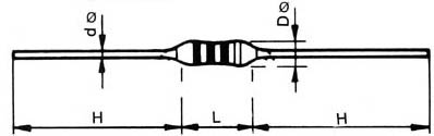 |
| DIMENSIONS(mm) in |
|
L |
D |
H |
d |
| 1/8W |
3.7±0.4 |
1.5±0.2 |
27MIN |
0.5±0.02 |
| 1/4W |
6.5±0.5 |
2.3±0.2 |
27MIN |
0.6±0.02 |
|
| PACKING: Resistors supplied on reels of 5,000 pieces per EIA RS-296-C |
| DIMENSIONS(mm.) |
In |
E. 530.5.....................
F. 6.6±0.5..................
P1.5.08±0.4...............
Pn.500±4..................
n:100 spacings
L. 6.35±0.25.............. |
2.090±.020
2.600±.020
200±.015
19.685±.157
250±.010 |
|
| TEST |
TEST METHOD |
LIMITS |
| RESISTANCE |
<0.005 ohm |
|
| OPERATING TEMPERATURE |
-55℃ to +155℃ |
| MAX. CURRENT |
5. amps |
| MAX. WORKING VOLTAGE |
300Vdc |
| MAX. OVERLOAD VOLTAGE |
600Vdc |
| TEMPERATURE COEFFICIENT |
(PPM/℃) 0 to - 100 PPM |
| SHORT TIME OVERLOAD |
Apply 2.5 times the voltage rating for 5 sec |
NO VISIBLE DAMAGE |
| LOAD LIFE |
1,000 hrs. at 70℃ a direct voltage applied, cycles of 1.5 hrs. on
and 0.5 hrs. off throughout test |
△ R = 0.5% |
| TEMPERATURE CYCLING |
5 cycles of 30 min. duration at the extremes of temp range,
maximum and minimum, measurement of ohmic valure 4 hrs.
after completion of test |
△ R = 0.5% |
| DIELECTRIC STRENGTH |
Using a 90°"V" shaped conductive block apply 100V minimum,
Increasing 100V/sec. For 5 sec. |
△ R = 0.5% |
| HUMIDITY |
350 hrs. at 40℃,90to 95% Rh |
△ R = 0.5% |
| SOLDERABILITY |
Dipped in Sn / Pb (60/40)at 235°,5sce. 1.5mm from the body |
95% OF TESTED SURFACE
COVERED |
| VIBRATION |
By Mil STD.202,201A |
|
| TERMINAL ROBUSTNESS |
Traction, applied 2.5kg.for 10 sec. Bends,2 bends 90℃applying
Load to terminals of 0.5kg. Twist, 2 successive turns 180°, 6mm
From body |
NO VISIBLE DAMAGE |
| RESISTANCE TO SOLVENTS |
Trichlorethylene , TMC as the most aggressives for 60 sec. At
Boiling point. |
NO VISIBLE DAMAGE |
|
APPLICATIONS
Molded jumper wires or crossovers, as they are sometimes called, are basically interconnection devices between points on a PC board.
Generally they are used for the following reasons:
- Inability to connect two points on a PC board due to other circuit paths which must be crossed over.
- An after-the-fact design change that requires new point connections.
- Circuit tuning by changing point connections.
- Optional feature applications.
|
|